
Page 165 - Rotating Machinery Pratical Solutions to Unbalance and Misalignment
P. 165
Advanced Machine Alignment
operational and the catenary effect removed, the two shafts will be
in alignment.
As the stationary machine becomes operational, its centerline
will align with the final alignment line. However, while it is at
rest, the adjustable machine must be referenced to its cold, or rest
position.
Step 2. Next, the rim reading is divided by two and has its alge-
braic sign changed. It is then marked off from the current position
of the stationary machine’s shaft centerline. A horizontal line is
drawn from this point to the line representing the stem of the face
indicator. The face reading is now laid off from this new point.
The two readings’ points are now connected with a line that ex-
tends beyond the adjustable machine’s outboard foot line.
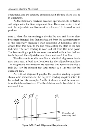
The distance from this new line to the final alignment line is
now measured at both foot locations for the adjustable machine.
The magnitude and direction are recorded and found to be plus 3
mils (+3) for the inboard foot and minus 12 (–12) mils for the
outboard foot.
As with all alignment graphs, the positive reading requires
shims to be removed and the negative reading requires shims to
be added. In this example, 3 mils of shims would be removed
from the inboard foot and 12 mils of shims would be added to the
outboard foot.
R F IB OB
IBB
Centerline of
+3 stationary shaff
0
–12
Figure 8-31. Final Alignment Requirements