
Page 170 - Rotating Machinery Pratical Solutions to Unbalance and Misalignment
P. 170
Rotating Machinery: Practical Solutions
Once the indicator fixtures are properly assembled on the
machine, and a trial set of readings taken to assure the fixture
clears the structure when rotated a full 360 degrees, its location on
the two shafts should be clearly marked. The fixtures are now
removed from the machine and placed on a ridged pipe or shaft
to determine bar sag. Note that in this method, both indicators
read a rim value, and thus both indicator fixtures must have their
bar sag accounted for.
BAR SAG
Once again, determining the bar sag is a straightforward
process. The indicators are set to zero in the 6 o’clock position and
rotated to the 12 o’clock position where the bar sag is read. Be sure
to determine the proper bar sag for each indicator fixture. Even
though the two fixtures are assembled the same, they may have
different amounts of sag.
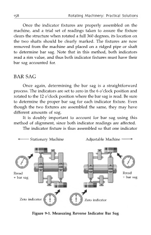
It is doubly important to account for bar sag using this
method of alignment, since both indicator readings are affected.
The indicator fixture is thus assembled so that one indicator
Stationary Machine Adjustable Machine
Rread Rread
+ bar sag + bar sag
Zero indicator Zero indicator
Figure 9-1. Measuring Reverse Indicator Bar Sag