
Page 175 - Rotating Machinery Pratical Solutions to Unbalance and Misalignment
P. 175
Reverse Indicator Alignment
scale and the more time taken to assure the drawn lines intersect
the indicator points at their centers, the more accurate the results.
CALCULATOR METHOD
As with the rim and face method, there is a simplified calcu-
lator method. Figure 9-5 shows the key strokes for this solution.
If the same machine measurements are used, and the indica-
tor readings from the reverse indicator example are input, Figure
9-6 shows the results.
The calculation method indicates 0.4 mils to be removed from
the inboard foot and 5.6 mils to be added to the outboard foot.
Both methods indicate the same basic required changes.
The calculator method is slightly more accurate in this case.
If a larger scale were used in the graphical method, the exact same
results would occur. However, adding or subtracting less than 1
mil is not practical, and in this example, 6 mils would be added
to the outboard foot and no change would be made to the inboard
foot.
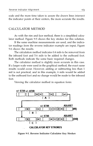
Viewing the calculator method in equation form:
Figure 9-5. Reverse Indicator Calculator Key Strokes