
Page 171 - Rotating Machinery Pratical Solutions to Unbalance and Misalignment
P. 171
Reverse Indicator Alignment
is placed on each machine. Figure 9-1 shows how the bar sag is
determined for reverse indicator method.
Once the bar sag values have been determined and recorded,
assure that both indicators are set to the plus bar sag when they
are in the 12 o’clock position. No further action is required to
compensate for bar sag.
The fixtures can now be reassembled to the machine, using
the reference marks as guides. An initial set of readings can now
be taken to assure the fixtures are properly assembled and suffi-
ciently ridged to return the indicators to their plus bar sag read-
ings at 12 o’clock, after being rotated 360 degrees.
MACHINE MEASUREMENTS
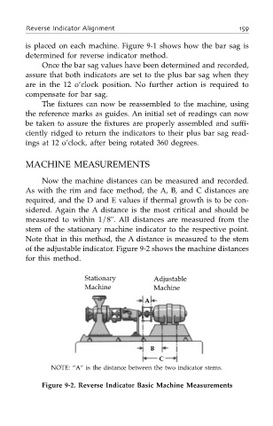
Now the machine distances can be measured and recorded.
As with the rim and face method, the A, B, and C distances are
required, and the D and E values if thermal growth is to be con-
sidered. Again the A distance is the most critical and should be
measured to within 1/8". All distances are measured from the
stem of the stationary machine indicator to the respective point.
Note that in this method, the A distance is measured to the stem
of the adjustable indicator. Figure 9-2 shows the machine distances
for this method.
Stationary Adjustable
Machine Machine
A
B
C
NOTE: “A” is the distance between the two indicator stems.
Figure 9-2. Reverse Indicator Basic Machine Measurements