
Page 180 - Rotating Machinery Pratical Solutions to Unbalance and Misalignment
P. 180
Rotating Machinery: Practical Solutions
on the outboard foot line is 2 mils below the stationary machine
hot centerline, the final alignment will place the adjustable ma-
chine outboard foot high by two mils.
Since the cold alignment was worked out in Example 9-1 and
found to require no change on the inboard foot and that 6 mils
were required to be added to the outboard foot, the two results are
simply added together. In this example no change to the inboard
foot was required from either calculation.
Therefore no change will be made to the inboard foot. The
outboard foot required 6 mils of shims to be added for the cold
alignment and required to be set an additional 2 mils high to
compensate for the hot alignment. Adding these two together re-
quires a total of eight (+8) mils to be added to the outboard foot.
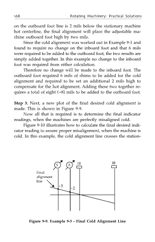
Step 3. Next, a new plot of the final desired cold alignment is
made. This is shown in Figure 9-9.
Now all that is required is to determine the final indicator
readings, when the machines are perfectly misaligned cold.
Figure 9-10 illustrates how to calculate the final desired indi-
cator reading to assure proper misalignment, when the machine is
cold. In this example, the cold alignment line crosses the station-
S ▲ A ▲ IB IB
Final
alignment
line
+5
• +2
▲
•
Figure 9-9. Example 9-3 - Final Cold Alignment Line