
Page 94 - Safety Risk Management for Medical Devices
P. 94
Risk Analysis Techniques 73
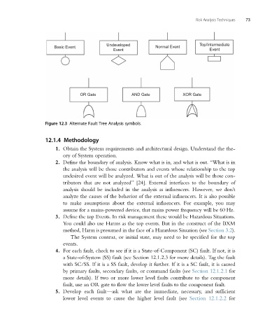
Undeveloped Top/Intermediate
Basic Event Normal Event
Event Event
OR Gate AND Gate XOR Gate
Figure 12.3 Alternate Fault Tree Analysis symbols.
12.1.4 Methodology
1. Obtain the System requirements and architectural design. Understand the the-
ory of System operation.
2. Define the boundary of analysis. Know what is in, and what is out. “What is in
the analysis will be those contributors and events whose relationship to the top
undesired event will be analyzed. What is out of the analysis will be those con-
tributors that are not analyzed” [24]. External interfaces to the boundary of
analysis should be included in the analysis as influencers. However, we don’t
analyze the causes of the behavior of the external influencers. It is also possible
to make assumptions about the external influencers. For example, you may
assume for a mains-powered device, that mains power frequency will be 60 Hz.
3. Define the top Events. In risk management these would be Hazardous Situations.
You could also use Harms as the top events. But in the construct of the BXM
method, Harm is presumed in the face of a Hazardous Situation (see Section 3.2).
The System context, or initial state, may need to be specified for the top
events.
4. For each fault, check to see if it is a State-of-Component (SC) fault. If not, it is
a State-of-System (SS) fault (see Section 12.1.2.3 for more details). Tag the fault
with SC/SS. If it is a SS fault, develop it further. If it is a SC fault, it is caused
by primary faults, secondary faults, or command faults (see Section 12.1.2.1 for
more details). If two or more lower level faults contribute to the component
fault, use an OR gate to flow the lower level faults to the component fault.
5. Develop each fault—ask what are the immediate, necessary, and sufficient
lower level events to cause the higher level fault (see Section 12.1.2.2 for