
Page 136 - Satellite Communications, Fourth Edition
P. 136
116 Chapter Five
E
k
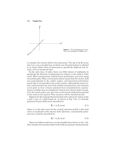
Figure 5.1 Vector diagram for a trans-
verse electromagnetic (TEM) wave.
H
to consider the electric field in this discussion. The tip of the E vector
may trace out a straight line, in which case the polarization is referred
to as linear. Other forms of polarization, specifically elliptical and cir-
cular, will be introduced later.
In the early days of radio, there was little chance of ambiguity in
specifying the direction of polarization in relation to the surface of the
earth. Most transmissions utilized linear polarization and were along
terrestrial paths. Thus vertical polarization meant that the electric field
was perpendicular to the earth’s surface, and horizontal polarization
meant that it was parallel to the earth’s surface. Although the terms ver-
tical and horizontal are used with satellite transmissions, the situation
is not quite so clear. A linear polarized wave transmitted by a geosta-
tionary satellite may be designated vertical if its electric field is paral-
lel to the earth’s polar axis, but even so the electric field will be parallel
to the earth at the equator. This situation will be clarified shortly.
Suppose for the moment that horizontal and vertical are taken as the
x and y axes of a right-hand set, as shown in Fig. 5.2a. A vertically
polarized electric field can be described as
E â E sinwt (5.1)
y
y
y
where â is the unit vector in the vertical direction and E is the peak
y
y
value or amplitude of the electric field. Likewise, a horizontally polar-
ized wave could be described by
E â E sinwt (5.2)
x
x
x
These two fields would trace out the straight lines shown in Fig. 5.2b.
Now consider the situation where both fields are present simultaneously.