
Page 137 - Satellite Communications, Fourth Edition
P. 137
Polarization 117
y +E y y
2
|E| = E +E y 2
x
â y
â x
x –E x +E x x
z-axis
out of page
–E y
(a) (b) (c)
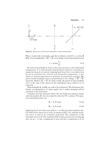
Figure 5.2 Horizontal and vertical components of linear polarization.
These would add vectorially, and the resultant would be a vector E
2 2
(Fig. 5.2c) of amplitude 2E E , at an angle to the horizontal given by
x y
E y
a arctan (5.3)
E x
E varies sinusoidally in time in the same manner as the individual
components. It is still linearly polarized but cannot be classified as
simply horizontal or vertical. Arguing back from this, it is evident that
E can be resolved into vertical and horizontal components, a fact
which is of great importance in practical transmission systems. The
2
power in the resultant wave is proportional to the voltage 2E E 2 y ,
x
2 2
squared, which is E x E y . In other words, the power in the resultant
wave is the sum of the powers in the individual waves, which is to be
expected.
More formally, E and E are said to be orthogonal. The dictionary def-
y
x
inition of orthogonal is at right angles, but a wider meaning will be
attached to the word later.
Consider now the situation where the two fields are equal in ampli-
tude (denoted by E), but one leads the other by 90° in phase. The equa-
tions describing these are
E â E sinwt (5.4a)
y
y
E â E coswt (5.4b)
x
x
Applying Eq. (5.3) in this case yields a wt. The tip of the resultant elec-
tric field vector traces out a circle, as shown in Fig. 5.3a, and the result-
ant wave is said to be circularly polarized. The amplitude of the
resultant vector is E. The resultant field in this case does not go through
zero. At wt 0, the y component is zero and the x component is E. At