
Page 138 - Satellite Communications, Fourth Edition
P. 138
118 Chapter Five
t = 90°
E
t = 180° t t = 0
t = 270°
(a)
RHC Classical optics
IEEE viewpoint viewpoint
E
z
(b)
LHC Classical optics
IEEE viewpoint viewpoint
E
z
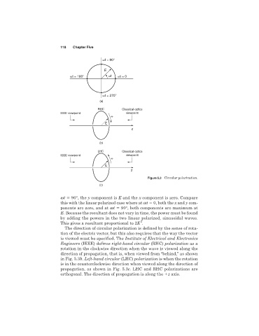
Figure 5.3 Circular polarization.
(c)
wt 90°, the y component is E and the x component is zero. Compare
this with the linear polarized case where at wt 0, both the x and y com-
ponents are zero, and at wt 90°, both components are maximum at
E. Because the resultant does not vary in time, the power must be found
by adding the powers in the two linear polarized, sinusoidal waves.
2
This gives a resultant proportional to 2E .
The direction of circular polarization is defined by the sense of rota-
tion of the electric vector, but this also requires that the way the vector
is viewed must be specified. The Institute of Electrical and Electronics
Engineers (IEEE) defines right-hand circular (RHC) polarization as a
rotation in the clockwise direction when the wave is viewed along the
direction of propagation, that is, when viewed from “behind,” as shown
in Fig. 5.3b. Left-hand circular (LHC) polarization is when the rotation
is in the counterclockwise direction when viewed along the direction of
propagation, as shown in Fig. 5.3c. LHC and RHC polarizations are
orthogonal. The direction of propagation is along the z axis.