
Page 183 - Satellite Communications, Fourth Edition
P. 183
Antennas 163
S S S
f f f
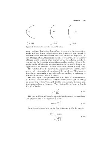
< 0.25 = 0.25 > 0.25
D D D
Figure 6.18 Position of the focus for various f/D values.
nearly uniform illumination, but spillover increases. In the transmitting
mode, spillover is the radiation from the primary antenna which is
. In
directed toward the reflector but which lies outside the angle 2 0
satellite applications, the primary antenna is usually a horn (or an array
of horns, as will be shown later) pointed toward the reflector. In order to
compensate for the space attenuation described earlier, higher-order
modes can be added to the horn feed so that the horn-radiation pattern
approximates the inverse of the space attenuation function (Chang, 1989).
The radiation from the horn will be a spherical wave, and the phase
center will be the center of curvature of the wavefront. When used as
the primary antenna for a parabolic reflector, the horn is positioned so
that the phase center lies on the focus.
The focal length can be given in terms of the depth of the reflector and
its diameter. It is sometimes useful to know the focal length for setting
up a receiving system. The depth d is the perpendicular distance from
the aperture plane to the vertex. This relationship is shown in App. B
[Eq. (B.37)] to be
D 2
f (6.30)
16d
The gain and beamwidths of the paraboloidal antenna are as follows.
The physical area of the aperture plane is
D 2
Area (6.31)
4
From the relationships given by Eqs. (6.14) and (6.15), the gain is
4
G 2 area
I
l
2 (6.32)
a D b
I
l