
Page 184 - Satellite Communications, Fourth Edition
P. 184
164 Chapter Six
The radiation pattern for the paraboloidal reflector is similar to that
developed in Example 6.1 for the rectangular aperture, in that there is
a main lobe and a number of sidelobes, although there will be differences
in detail. In practice, the sidelobes are accounted for by an envelope func-
tion as described in Sec. 13.2.4. Useful approximate formulas for the
half-power beamwidth and the beamwidth between the first nulls
(BWFN) are
l
HPBW > 70 (6.33)
D
BWFN > 2HPBW (6.34)
In these relationships, the beamwidths are given in degrees. The
paraboloidal antenna described so far is center-fed, in that the primary
horn is pointed toward the center of the reflector. With this arrangement
the primary horn and its supports present a partial blockage to the
reflected wave. The energy scattered by the blockage is lost from the
main lobe, and it can create additional sidelobes. One solution is to use
an offset feed as described in Sec. 6.14.
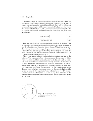
The wave from the primary radiator induces surface currents in the
reflector. The curvature of the reflector causes the currents to follow
curved paths so that both horizontal and vertical components are pres-
ent, even where the incident wave is linearly polarized in one or other
of these directions. The situation is sketched for the case of vertical
polarization in Fig. 6.19. The resulting radiation consists of copolarized
and cross-polarized fields. The symmetry of the arrangement means
that the cross-polarized component is zero in the principal planes (the
E and H planes). Cross-polarization peaks in the 45° planes,
assuming a coordinate system as shown in Fig. 6.5a. Sketches of the
copolar and cross-polar radiation patterns for the 45° planes are shown
in Fig. 6.20.
Figure 6.19 Current paths in a
paraboloidal reflector for linear
polarization.