
Page 185 - Satellite Communications, Fourth Edition
P. 185
Antennas 165
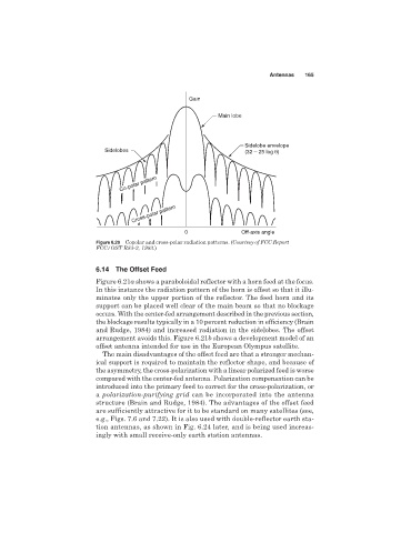
Gain
Main lobe
Sidelobe envelope
Sidelobes (32 – 25 log θ)
Co-polar pattern
Cross-polar pattern
0 Off-axis angle
Figure 6.20 Copolar and cross-polar radiation patterns. (Courtesy of FCC Report
FCC/OST R83-2, 1983.)
6.14 The Offset Feed
Figure 6.21a shows a paraboloidal reflector with a horn feed at the focus.
In this instance the radiation pattern of the horn is offset so that it illu-
minates only the upper portion of the reflector. The feed horn and its
support can be placed well clear of the main beam so that no blockage
occurs. With the center-fed arrangement described in the previous section,
the blockage results typically in a 10 percent reduction in efficiency (Brain
and Rudge, 1984) and increased radiation in the sidelobes. The offset
arrangement avoids this. Figure 6.21b shows a development model of an
offset antenna intended for use in the European Olympus satellite.
The main disadvantages of the offset feed are that a stronger mechan-
ical support is required to maintain the reflector shape, and because of
the asymmetry, the cross-polarization with a linear polarized feed is worse
compared with the center-fed antenna. Polarization compensation can be
introduced into the primary feed to correct for the cross-polarization, or
a polarization-purifying grid can be incorporated into the antenna
structure (Brain and Rudge, 1984). The advantages of the offset feed
are sufficiently attractive for it to be standard on many satellites (see,
e.g., Figs. 7.6 and 7.22). It is also used with double-reflector earth sta-
tion antennas, as shown in Fig. 6.24 later, and is being used increas-
ingly with small receive-only earth station antennas.