
Page 210 - Satellite Communications, Fourth Edition
P. 210
190 Chapter Six
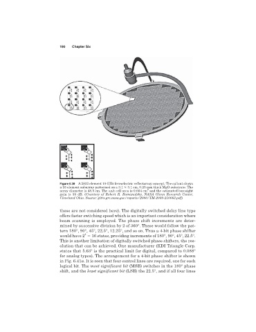
Figure 6.39 A 2832 element 19 GHz ferroelectric reflectarray concept. The callout shows
a 16 element subarray patterned on a 3.1 3.1 cm, 0.25 mm thick MgO substrate. The
2
array diameter is 48.5 cm. The unit cell area is 0.604 cm and the estimated boresight
gain is 39 dB. (Courtesy of Robert R. Romanofsky, NASA Glenn Research Center,
Cleveland Ohio. Source: gltrs.grc.nasa.gov/reports/2000/TM-2000-210063.pdf)
these are not considered here). The digitally switched delay line type
offers faster switching speed which is an important consideration where
beam scanning is employed. The phase shift increments are deter-
mined by successive division by 2 of 360°. These would follow the pat-
tern 180°, 90°, 45°, 22.5°, 12.25°, and so on. Thus a 4-bit phase shifter
4
would have 2 16 states, providing increments of 180°, 90°, 45°, 22.5°.
This is another limitation of digitally switched phase shifters, the res-
olution that can be achieved. One manufacturer (KDI Triangle Corp.
states that 5.63° is the practical limit for digital, compared to 0.088°
for analog types). The arrangement for a 4-bit phase shifter is shown
in Fig. 6.41a. It is seen that four control lines are required, one for each
logical bit. The most significant bit (MSB) switches in the 180° phase
shift, and the least significant bit (LSB) the 22.5°, and if all four lines