Page 211 - Satellite Communications, Fourth Edition
P. 211

Antennas   191


                                          Varactor bias


                                    Varactor diodes              L


                                              W
                                            (top view)


                                              −
                                       e r   +
                                                                   h
                                            (side view)


                                       0.58l


                                   1                                               5
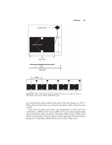
                              Figure 6.40  Phase shift using varactor diodes. (Courtesy of L. Boccia. Source:
                              www.ansoft.com/news/articles/ICEAA2001.pdf)


                              are activated the phase shift is the sum of the four delays, or 337.5°.
                              With all four delay lines out of circuit the phase shift is back to zero,
                              or 360°.
                                Care must be taken how “bits” are interpreted. A “three bit” line
                              would have a MSB of 180° and a LSB of 45° and would require three
                              logic control lines. However in the 3-bit phase shifter shown in Fig. 6.41b
                              positive and negative control voltages can be applied to the control lines,
                              giving rise to the phase shifts shown in the table of Fig. 6.41c.
   206   207   208   209   210   211   212   213   214   215   216