
Page 242 - Satellite Communications, Fourth Edition
P. 242
222 Chapter Seven
used in ground stations, the magnetic field can be provided by means
of a solenoid and dc power supply. The comparatively large size and high
power consumption of solenoids make them unsuitable for use aboard
satellites, and lower-power TWTs are used which employ permanent-
magnet focusing.
The rf signal to be amplified is coupled into the helix at the end near-
est the cathode and sets up a traveling wave along the helix. The elec-
tric field of the wave will have a component along the axis of the helix.
In some regions, this field will decelerate the electrons in the beam, and
in others it will accelerate them so that electron bunching occurs along
the beam. The average beam velocity, which is determined by the dc
potential on the tube collector, is kept slightly greater than the phase
velocity of the wave along the helix. Under these conditions, an energy
transfer takes place, kinetic energy in the beam being converted to
potential energy in the wave. The wave actually will travel around the
helical path at close to the speed of light, but it is the axial component
of wave velocity which interacts with the electron beam. This component
is less than the velocity of light approximately in the ratio of helix pitch
to circumference. Because of this effective reduction in phase velocity,
the helix is referred to as a slowwave structure.
The advantage of the TWT over other types of tube amplifiers is that
it can provide amplification over a very wide bandwidth. Input levels
to the TWT must be carefully controlled, however, to minimize the
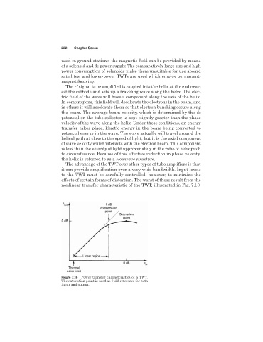
effects of certain forms of distortion. The worst of these result from the
nonlinear transfer characteristic of the TWT, illustrated in Fig. 7.18.
Figure 7.18 Power transfer characteristics of a TWT.
The saturation point is used as 0-dB reference for both
input and output.