
Page 244 - Satellite Communications, Fourth Edition
P. 244
224 Chapter Seven
Where only a single carrier is present, it may be passed through a hard
limiter before being amplified in the TWT. The hard limiter is a circuit
which clips the carrier amplitude close to the zero baseline to remove
any amplitude modulation. The FM is preserved in the zero crossover
points and is not affected by the limiting.
A TWT also may be called on to amplify two or more carriers simul-
taneously, this being referred to as multicarrier operation. The AM/PM
conversion is then a complicated function of carrier amplitudes, but in
addition, the nonlinear transfer characteristic introduces a more seri-
ous form of distortion known as intermodulation distortion. The non-
linear transfer characteristic may be expressed as a Taylor series
expansion which relates input and output voltages:
2
3
ae be ce c (7.1)
e 0 i i i
Here, a, b, c, and so on are coefficients which depend on the transfer char-
acteristic, e is the output voltage, and e is the input voltage, which con-
i
0
3
sists of the sum of the individual carriers. The third-order term is ce .
i
This and higher-order odd-power terms give rise to intermodulation
products, but usually only the third-order contribution is significant.
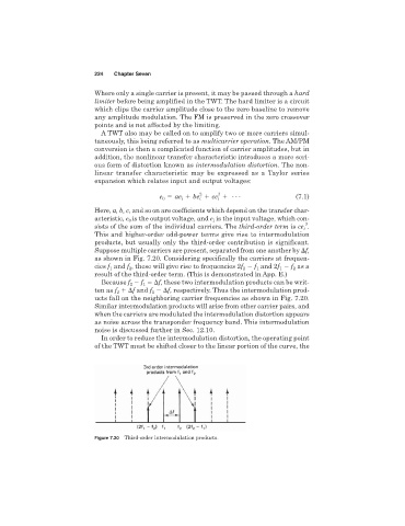
Suppose multiple carriers are present, separated from one another by f,
as shown in Fig. 7.20. Considering specifically the carriers at frequen-
cies f and f , these will give rise to frequencies 2f f and 2f f as a
1
2
2
1
1
2
result of the third-order term. (This is demonstrated in App. E.)
Because f f f, these two intermodulation products can be writ-
1
2
ten as f f and f f, respectively. Thus the intermodulation prod-
2
1
ucts fall on the neighboring carrier frequencies as shown in Fig. 7.20.
Similar intermodulation products will arise from other carrier pairs, and
when the carriers are modulated the intermodulation distortion appears
as noise across the transponder frequency band. This intermodulation
noise is discussed further in Sec. 12.10.
In order to reduce the intermodulation distortion, the operating point
of the TWT must be shifted closer to the linear portion of the curve, the
Figure 7.20 Third-order intermodulation products.