
Page 245 - Satellite Communications, Fourth Edition
P. 245
The Space Segment 225
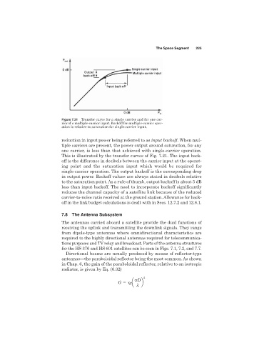
Figure 7.21 Transfer curve for a single carrier and for one car-
rier of a multiple-carrier input. Backoff for multiple-carrier oper-
ation is relative to saturation for single-carrier input.
reduction in input power being referred to as input backoff. When mul-
tiple carriers are present, the power output around saturation, for any
one carrier, is less than that achieved with single-carrier operation.
This is illustrated by the transfer curves of Fig. 7.21. The input back-
off is the difference in decibels between the carrier input at the operat-
ing point and the saturation input which would be required for
single-carrier operation. The output backoff is the corresponding drop
in output power. Backoff values are always stated in decibels relative
to the saturation point. As a rule of thumb, output backoff is about 5 dB
less than input backoff. The need to incorporate backoff significantly
reduces the channel capacity of a satellite link because of the reduced
carrier-to-noise ratio received at the ground station. Allowance for back-
off in the link budget calculations is dealt with in Secs. 12.7.2 and 12.8.1.
7.8 The Antenna Subsystem
The antennas carried aboard a satellite provide the dual functions of
receiving the uplink and transmitting the downlink signals. They range
from dipole-type antennas where omnidirectional characteristics are
required to the highly directional antennas required for telecommunica-
tions purposes and TV relay and broadcast. Parts of the antenna structures
for the HS 376 and HS 601 satellites can be seen in Figs. 7.1, 7.2, and 7.7.
Directional beams are usually produced by means of reflector-type
antennas—the paraboloidal reflector being the most common. As shown
in Chap. 6, the gain of the paraboloidal reflector, relative to an isotropic
radiator, is given by Eq. (6.32)
2
G a D b
I
l