
Page 315 - Satellite Communications, Fourth Edition
P. 315
Digital Signals 295
A
t
(a)
A
t
Sampling
instant
(b)
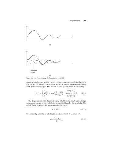
Figure 10.9 (a) Pulse ringing. (b) Sampling to avoid ISI.
spectrum is known as the raised cosine response, which is shown in
Fig. 10.10. Although a theoretical model, it can be approached closely
with practical designs. The raised cosine spectrum is described by
1 for f , f 1
psf 2 f d
1
Vs f d 5 •0.5a1 1 cos b for f , f , B (10.9)
1
B 2 f 1
0 for B , f
The frequencies f and B are determined by the symbol rate and a design
1
parameter known as the rolloff factor, denoted here by the symbol . The
rolloff factor is a specified parameter in the range
0 1 (10.10)
In terms of and the symbol rate, the bandwidth B is given by
1
B R sym (10.11)
2