
Page 362 - Satellite Communications, Fourth Edition
P. 362
342 Chapter Eleven
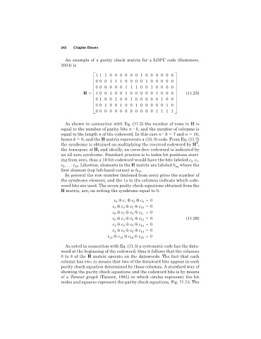
An example of a parity check matrix for a LDPC code (Summers,
2004) is
1 110000001000000
0 001110000100000
0 000001110010000
H 5 G1 001001000001000 W (11.25)
0 100100100000100
0 010010010000010
0 000000000001111
As shown in connection with Eq. (11.5) the number of rows in H is
equal to the number of parity bits n k, and the number of columns is
equal to the length n of the codeword. In this case n k 7 and n 16,
hence k 9, and the H matrix represents a (16, 9) code. From Eq. (11.7)
T
the syndrome is obtained on multiplying the received codeword by H ,
the transpose of H, and ideally, an error-free codeword is indicated by
an all-zero syndrome. Standard practice is to index bit positions start-
ing from zero, thus a 16-bit codeword would have the bits labeled c , c ,
0
1
c , . . . c . Likewise, elements in the H matrix are labeled h where the
15
pq
2
first element (top left-hand corner) is h .
00
In general the row number (indexed from zero) gives the number of
the syndrome element, and the 1s in the columns indicate which code-
word bits are used. The seven parity check equations obtained from the
H matrix, are, on setting the syndrome equal to 0.
{ c { c { c 0
c 0 1 2 9
c { c { c { c 10 0
3
4
5
c { c { c { c 11 0
6
8
7
c { c { c { c 12 0 (11.26)
6
3
0
c { c { c { c 13 0
1
4
7
c { c { c { c 14 0
5
8
2
c 12 { c 13 { c 14 { c 15 0
As noted in connection with Eq. (11.3) a systematic code has the data-
word at the beginning of the codeword, thus it follows that the columns
0 to 8 of the H matrix operate on the datawords. The fact that each
column has two 1s means that two of the dataword bits appear in each
parity check equation determined by these columns. A standard way of
showing the parity check equations and the codeword bits is by means
of a Tanner graph (Tanner, 1981) in which circles represent the bit
nodes and squares represent the parity check equations, Fig. 11.13. The