
Page 359 - Satellite Communications, Fourth Edition
P. 359
Error Control Coding 339
codes, (known as Turbo Product codes or TPCs, see Comtech, 2002).
However the more common arrangement is to use parallel concatenation
using convolution encoders. Because of the continuous nature of convo-
lution coding, data and code sequences rather than words are involved.
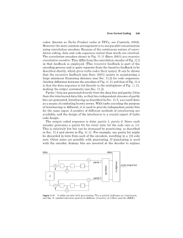
The convolution encoders shown in Fig. 11.11 (Burr, 2001) are recursive
convolution encoders. They differ from the convolution encoder of Fig. 11.2
in that feedback is employed. (This recursive feedback is part of the
encoding process and is quite separate from the iterative feedback to be
described shortly, which gives turbo codes their name). It can be shown
that the recursive feedback (see Burr, 2001) assists in maintaining a
large minimum Hamming distance (see Sec. 11.2) for code sequences.
Another difference between the encoders of Fig. 11.11 and that of Fig. 11.2
is that the data sequence is fed directly to the multiplexer of Fig. 11.11,
making the output systematic (see Sec. 11.2).
Parity-1 bits are generated directly from the data bits and parity-2 bits
from the interleaved data bits, so that two independent streams of parity
bits are generated. Interleaving as described in Sec. 11.5, was used there
as a means of combating bursty errors. With turbo encoding the purpose
of interleaving is different, it is used to provide independent parity bits
for the same input. A number of different methods of interleaving are
available, and the design of the interleaver is a crucial aspect of turbo
code design.
The output coded sequence is data, parity-1, parity-2. Since each
encoder generates a parity bit for every data bit the code rate is 1/3.
This is relatively low but can be increased by puncturing, as described
in Sec. 11.4 and shown in Fig. 11.11. For example, one parity bit might
be discarded in turn from each of the encoders, resulting in a 1/2 code
rate. Other rates are possible with puncturing. If puncturing is used
with the encoder, dummy bits are inserted at the decoder to replace
data data
+
parity 1
+ multiplexer code sequence
puncture
+
p
parity 2
+
+
+
Figure 11.11 A turbo encoder with puncturing. The symbol indicates an interleaver,
and the { symbol indicates modulo-2 addition. (Courtesy of A Burr and the IEEE.)