Page 360 - Satellite Communications, Fourth Edition
P. 360

340  Chapter Eleven

                              those discarded. The dummy bit level is set midway between the binary
                              1 and 0 levels, so they do not affect the decoding process.
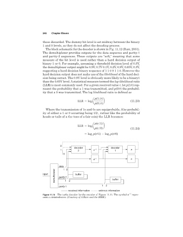
                                The block schematic for the decoder is shown in Fig. 11.12 (Burr, 2001).
                              The demultiplexer provides outputs for the data sequence and parity-1
                              and parity-2 sequences. These outputs are “soft,” meaning that some
                              measure of the bit level is used rather than a hard decision output of
                              binary 1 or 0. For example, assuming a threshold decision level of 0.5V,
                              the demultiplexer output might be 0.9V, 0.7V 0.1V, 0.2V, 0.9V, 0.65V, 0.3V,
                              suggesting a hard decision binary sequence of 1 1 0 0 1 1 0. However the
                              hard decision output does not make use of the likelihood of the hard deci-
                              sion being correct. The 0.9V level is obviously more likely to be a binary1
                              than the 0.65V level. Astatistical measure termed the log-likelihood ratio
                              (LLR) is most commonly used. For a given received value r,let p(1/r) rep-
                              resent the probability that a 1 was transmitted, and p(0/r) the probabil-
                              ity that a 0 was transmitted. The log likelihood ratio is defined as

                                                                p(1>r)
                                                               a      b                 (11.23)
                                                     LLR   log e
                                                                p(0>r)
                                Where the transmission of 1s and 0s are equiprobable, (the probabil-
                              ity of either a 1 or 0 occurring being 1/2 , rather like the probability of
                              heads or tails of a the toss of a fair coin) the LLR becomes:

                                                                p(r>1)
                                                               a      b
                                                     LLR   log e
                                                                p(r>0)                  (11.24)
                                                           log p(r/1)   log e  p(r/0)
                                                              e


                                         2
                                                   decoder                 decoder
                                         1           2         p −1           1         p
                                           0
                                                               p −1                     p

                                        data 1 2
                                      demultiplexer  parity 2  2            buffer
                              input                buffer

                                            1

                                        parity   1                   1  2
                                               received information  extrinsic information
                              Figure 11.12 The turbo decoder for the encoder of Figure 11.11. The symbol    1  repre-
                              sents a deinterleaver. (Courtesy of A Burr and the IEEE.)
   355   356   357   358   359   360   361   362   363   364   365