
Page 378 - Schaum's Outline of Theory and Problems of Applied Physics
P. 378
CHAP. 29] ALTERNATING-CURRENT CIRCUITS 363
SOLVED PROBLEM 29.20
A coil connected to a 120-V, 25-Hz power line draws a current of 0.5 A and dissipates 50 W. (a) What is
its power factor? (b) What capacitance should be connected in series with the coil to increase the power
factor to 100 percent? (c) What would the current in the circuit be then? (d) How much power would the
circuit then dissipate?
(a) Since P = IV cos φ,
P 50 W
cos φ = = = 0.833 = 83.3%
IV (0.5A)(120 V)
(b) The power factor will be 100 percent at resonance, when X L = X C . The first step is to find X L , which can
be done from the formula tan φ = (X L − X C )/R. Hence X C = 0 and, since cos φ = 0.833, φ = 34 , and
◦
2
tan φ = 0.663. Since P = I R,
P 50 W
R = = = 200
I 2 (0.5A) 2
Hence, X L = R tan φ + X C = (200 )(0.663) + 0 = 133
This must also be the value of X C when f = 25 Hz, and so
1 1
C = = = 4.8 × 10 −5 F = 48 µF
2π f X C (2π)(25 Hz)(133 )
(c) At resonance Z = R,so
V V 120 V
I = = = = 0.6A
Z R 200
2
2
(d) P = I R = (0.6A) (200 ) = 72 W
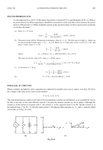
PARALLEL AC CIRCUITS
When a resistor, an inductor, and a capacitor are connected in parallel across an ac source, as in Fig. 29-12(a),
the voltage is the same across each circuit element:
V = V R = V L = V C
The total instantaneous current is the sum of the instantaneous currents in each branch, as in a parallel dc circuit,
but this is not true of the total effective current I because the branch currents are not in phase. Although the
◦
current I R in the resistor is in phase with V , the current I C in the capacitor leads V by 90 and the current I L in
◦
the inductor lags V by 90 . To find the total current I, the phasors that represent I R , I C , and I L must be added
vectorially, as in Fig. 29-12(b).
Fig. 29-12