
Page 379 - Schaum's Outline of Theory and Problems of Applied Physics
P. 379
364 ALTERNATING-CURRENT CIRCUITS [CHAP. 29
The branch currents in the parallel circuit of Fig. 29-12(a) are given by
V V V
I R = I C = I L =
R X C X L
Adding these currents vectorially with the help of the Pythagorean theorem gives
2
I = I + (I C − I L ) 2
R
The phase angle φ between current and voltage is specified by
I R
cos φ =
I
If I C is greater than I L , the current leads the voltage and the phase angle is considered positive; if I L is greater
than I C , the current lags the voltage and the phase angle is considered negative. The power dissipated in a parallel
ac circuit is given by the same formula as in a series circuit, namely,
P = IV cos φ
RESONANCE IN PARALLEL CIRCUITS
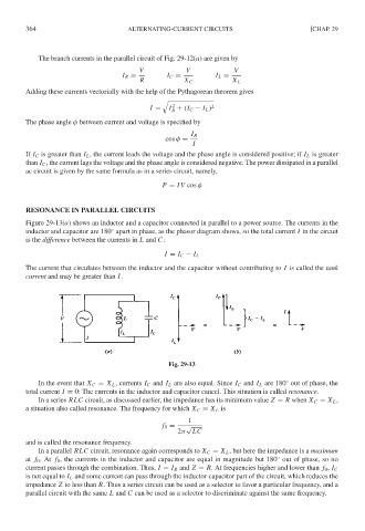
Figure 29-13(a) shows an inductor and a capacitor connected in parallel to a power source. The currents in the
inductor and capacitor are 180 apart in phase, as the phasor diagram shows, so the total current I in the circuit
◦
is the difference between the currents in L and C:
I = I C − I L
The current that circulates between the inductor and the capacitor without contributing to I is called the tank
current and may be greater than I.
Fig. 29-13
In the event that X C = X L , currents I C and I L are also equal. Since I C and I L are 180 out of phase, the
◦
total current I = 0: The currents in the inductor and capacitor cancel. This situation is called resonance.
In a series RLC circuit, as discussed earlier, the impedance has its minimum value Z = R when X C = X L ,
a situation also called resonance. The frequency for which X C = X L is
1
f 0 = √
2π LC
and is called the resonance frequency.
In a parallel RLC circuit, resonance again corresponds to X C = X L , but here the impedance is a maximum
◦
at f 0 .At f 0 , the currents in the inductor and capacitor are equal in magnitude but 180 out of phase, so no
current passes through the combination. Thus, I = I R and Z = R. At frequencies higher and lower than f 0 , I C
is not equal to I L and some current can pass through the inductor-capacitor part of the circuit, which reduces the
impedance Z to less than R. Thus a series circuit can be used as a selector to favor a particular frequency, and a
parallel circuit with the same L and C can be used as a selector to discriminate against the same frequency.