
Page 380 - Schaum's Outline of Theory and Problems of Applied Physics
P. 380
CHAP. 29] ALTERNATING-CURRENT CIRCUITS 365
SOLVED PROBLEM 29.21
The reactances of a coil and a capacitor connected in parallel and supplied by a 15-V, 1000-Hz power
source are, respectively, X L = 20 and X C = 30 . Find (a) the current in each component, (b) the
total current, (c) the impedance of the circuit, and (d) the phase angle and total power dissipated in the
circuit.
V 15 V V 15 V
(a) I L = = = 0.75 A I C = = = 0.5A
X L 20 X C 30
(b) I = I C − I L = 0.5A − 0.75 A =−0.25 A
◦
The minus sign means that the total current lags 90 behind the voltage [the opposite of the situation shown in
Fig. 29-13(b)] and can be disregarded in the other calculations.
V 15 V
(c) Z = = = 60
I 0.25 A
The impedance not only is greater than X L or X C but also is greater than their arithmetical sum.
◦
(d) Because the phase angle here is 90 , cos φ = cos 90 = 0 and the power drawn by the circuit is
◦
P = IV cos φ = 0
This conclusion follows from the absence of resistance in the circuit.
SOLVED PROBLEM 29.22
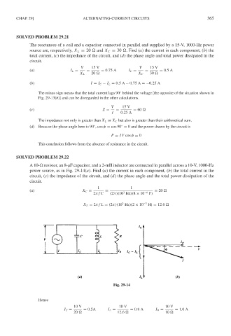
A 10- resistor, an 8-µF capacitor, and a 2-mH inductor are connected in parallel across a 10-V, 1000-Hz
power source, as in Fig. 29-14(a). Find (a) the current in each component, (b) the total current in the
circuit, (c) the impedance of the circuit, and (d) the phase angle and the total power dissipation of the
circuit.
1 1
(a) X C = = = 20
3
2π f C (2π)(10 Hz)(8 × 10 −6 F)
3
X L = 2π f L = (2π)(10 Hz)(2 × 10 −3 H) = 12.6
Fig. 29-14
Hence
10 V 10 V 10 V
I C = = 0.5A I L = = 0.8A I R = = 1.0A
20 12.6 10