
Page 376 - Schaum's Outline of Theory and Problems of Applied Physics
P. 376
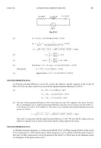
CHAP. 29]                     ALTERNATING-CURRENT CIRCUITS                            361


                                                    Fig. 29-11


              (a)                 X L = 2π f L = (2π)(60 HZ)(0.3H) = 113

                                         1              1
                                  X C =     =                      = 53
                                       2π f C  (2π)(60 Hz)(50 × 10 −6  F)

                                                           2
                                                                          2
                                                     2
                                          2
                                   Z =  R + (X L − X C ) =  80 + (113   − 53  ) = 100
                                                   V   120 V
              (b)                               I =  =       = 1.2A
                                                   Z   100
                                                   R    80
              (c)                            cos φ =  =     = 0.8 = 80%
                                                   Z   100
              (d)                 True Power = P = IV cos φ = (1.2A)(120 V)(0.8) = 115 W
                                           2
                                                    2
                  Alternatively,      P = I R = (1.2A) (80  ) = 115 W
              (e)                     Apparent power = IV = (1.2A)(120 V) = 144 VA


        SOLVED PROBLEM 29.16
              (a) Find the potential differences across the resistor, the inductor, and the capacitor in the circuit of
              Prob. 29.15 (b) Are these values in accord with the applied potential difference of 120 V?

              (a)                          V R = IR = (1.2A)(80  ) = 96 V
                                           V L = IX L = (1.2A)(113  ) = 136 V

                                           V C = IX C = (1.2A)(53  ) = 64 V

              (b) The sum of these potential differences is 296 V, more than twice the 120 V applied to the circuit. However,
                  this is a meaningless way to combine the potential differences since they are not in phase with one another: V L
                                          ◦
                      ◦
                  is 90 ahead of V R and V C is 90 behind V R . The correct way to find the total potential difference across the
                  circuit is as follows:


                                        2         2         2             2
                                 V =   V + (V L − V C ) =  (96 V) + (136 V − 64 V) = 120 V
                                        R
                  This result is in agreement with the applied potential difference of 120 V. We note that the voltage across an
                  inductor or capacitor in an ac circuit can be greater than the voltage applied to the circuit.
        SOLVED PROBLEM 29.17
              (a) Find the resonance frequency f 0 of the circuit of Prob. 29.15. (b) What current will flow in the circuit
              if it is connected to a 120-V power source whose frequency is f 0 ?(c) What will be the power factor in
              this case? (d) How much power will be dissipated by the circuit? (e) What must be the minimum rating
              in voltamperes of the power source now?