
Page 142 - Schaum's Outline of Theory and Problems of Electric Circuits
P. 142
FIRST-ORDER CIRCUITS
CHAP. 7]
Fig. 7-5 131
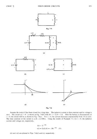
Fig. 7-6
Assume the switch S has been closed for a long time. The inductor current is then constant and its voltage is
zero. The circuit at t ¼ 0 is shown in Fig. 7-6(b) with ið0 Þ¼ 12=4 ¼ 3 A. After the battery is disconnected, at
t > 0, the circuit will be as shown in Fig. 7-6(c). For t > 0, the current decreases exponentially from 3 A to zero.
The time constant of the circuit is L=R ¼ð1=100Þ s. Using the results of Example 7.3, for t > 0, the inductor
current and voltage are, respectively,
iðtÞ¼ 3e 100t
vðtÞ¼ Lðdi=dtÞ¼ 30e 100t ðVÞ
iðtÞ and vðtÞ are plotted in Figs. 7-6(d) and (e), respectively.