
Page 165 - Schaum's Outline of Theory and Problems of Signals and Systems
P. 165
LAPLACE TRANSFORM AND CONTINUOUS-TIME LTI SYSTEMS [CHAP. 3
Taking the unilateral Laplace transform of Eq. (3.105), we obtain
Thus,
Using partial-fraction expansions, we obtain
Taking the inverse Laplace transform of Yl(s), we have
Notice that y(O+) = 2 = y(O) and y'(O+) = 1 = yl(0); and we can write y(f) as
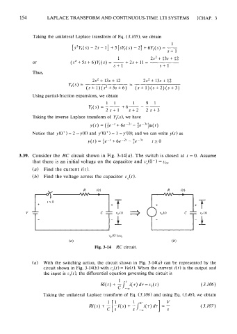
3.39. Consider the RC circuit shown in Fig. 3-14(a). The switch is closed at t = 0. Assume
that there is an initial voltage on the capacitor and uC(Om) = u,,.
(a) Find the current i(t).
(6) Find the voltage across the capacitor uc(t).
vc (0- )=v,
(a) (b)
Fig. 3-14 RC circuit.
(a) With the switching action, the circuit shown in Fig. 3-14(a) can be represented by the
circuit shown in Fig. 3-14(b) with i.f,(t) = Vu(t). When the current i(t) is the output and
the input is r,(t), the differential equation governing the circuit is
1
Ri(t) + -1' i(r) d~ = cs(t) (3.106)
C -,
Taking the unilateral Laplace transform of Eq. (3.106) and using Eq. (3.481, we obtain