
Page 167 - Schaum's Outline of Theory and Problems of Signals and Systems
P. 167
LAPLACE TRANSFORM AND CONTINUOUS-TIME LTI SYSTEMS [CHAP. 3
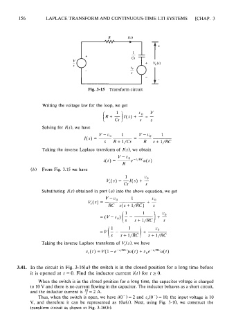
Fig. 3-15 Transform circuit,
Writing the voltage law for the loop, we get
Solving for I(s), we have
v-u, 1 v-u, 1
--
I(s) = - -
s R+ 1/Cs R s+ l/RC
Taking the inverse Laplace transform of I(s), we obtain
(b) From Fig.3.15 we have
Substituting I(s) obtained in part (a) into the above equation, we get
Taking the inverse Laplace transform of V,(s), we have
3.41. In the circuit in Fig. 3-16(a) the switch is in the closed position for a long time before
it is opened at t = 0. Find the inductor current i(t) for t 2 0.
When the switch is in the closed position for a long time, the capacitor voltage is charged
to 10 V and there is no current flowing in the capacitor. The inductor behaves as a short circuit,
and the inductor current is = 2 A.
Thus, when the switch is open, we have i(O-)= 2 and u,(O-) = 10; the input voltage is 10
V, and therefore it can be represented as lOu(t). Next, using Fig. 3-10, we construct the
transform circuit as shown in Fig. 3-16(b).