
Page 163 - Semiconductor For Micro- and Nanotechnology An Introduction For Engineers
P. 163
The Electromagnetic System
E (a) x E (b) x
B B
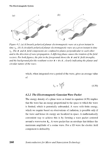
Figure 4.1. (a) A linearly polarized planar electromagnetic wave at a given instant in
t
time . (b) A circularly polarized planar electromagnetic wave at a given instant in time
0
t 0 . The and field components are confined to planes perpendicular to each other
B
E
and to the direction of wave propagation. A differing phase causes the rotation of the field
vectors. For both figures, the plot in the foreground shows the and field strengths,
E
B
and the background plot the resultant vector R = B + E , clearly indicating the planar and
circular nature of the wave.
which, when integrated over a period of the wave, gives an average value
of
2
ε E 0
0
v = ----------- (4.50)
E
2
4.2.2 The Electromagnetic Gaussian Wave Packet
The energy density of a plane wave as found in equation (4.50) implies
that the wave has an energy proportional to the space to which the wave
is limited, which is potentially unbounded. A wave with finite energy,
which we require based on observations of radiation, is possible only if
the wave and hence its energy are localized in space. A mathematically
convenient way to achieve this is by forming a wave packet centered
around a wavevector k . A wave packet has an envelope that defines the
0
maximum amplitude of a cosine wave. For a 1D wave the electric field
component is defined by
160 Semiconductors for Micro and Nanosystem Technology