
Page 302 - Sensing, Intelligence, Motion : How Robots and Humans Move in an Unstructured World
P. 302
THE CASE OF THE PPP (CARTESIAN) ARM 277
l 3
l 3max d g
e
f
P O 1
J 1 l 3
l 1 o c l
l 2max 2
J 3
O 3
l 1max J 2 l 2
a b
l 1
O 2
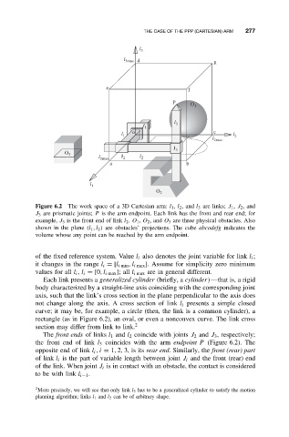
Figure 6.2 The work space of a 3D Cartesian arm: l 1 , l 2 ,and l 3 are links; J 1 , J 2 ,and
J 3 are prismatic joints; P is the arm endpoint. Each link has the front and rear end; for
example, J 3 is the front end of link l 2 . O 1 , O 2 ,and O 3 are three physical obstacles. Also
shown in the plane (l 1 ,l 2 ) are obstacles’ projections. The cube abcodefg indicates the
volume whose any point can be reached by the arm endpoint.
of the fixed reference system. Value l i also denotes the joint variable for link l i ;
it changes in the range l i = [l i min ,l i max ]. Assume for simplicity zero minimum
values for all l i , l i = [0,l i max ]; all l i max are in general different.
Each link presents a generalized cylinder (briefly, a cylinder)—that is, a rigid
body characterized by a straight-line axis coinciding with the corresponding joint
axis, such that the link’s cross section in the plane perpendicular to the axis does
not change along the axis. A cross section of link l i presents a simple closed
curve; it may be, for example, a circle (then, the link is a common cylinder), a
rectangle (as in Figure 6.2), an oval, or even a nonconvex curve. The link cross
section may differ from link to link. 2
The front ends of links l 1 and l 2 coincide with joints J 2 and J 3 , respectively;
the front end of link l 3 coincides with the arm endpoint P (Figure 6.2). The
opposite end of link l i ,i = 1, 2, 3, is its rear end. Similarly, the front (rear) part
of link l i is the part of variable length between joint J i and the front (rear) end
of the link. When joint J i is in contact with an obstacle, the contact is considered
to be with link l i−1 .
2 More precisely, we will see that only link l 3 has to be a generalized cylinder to satisfy the motion
planning algorithm; links l 1 and l 2 can be of arbitrary shape.