
Page 319 - Sensing, Intelligence, Motion : How Robots and Humans Move in an Unstructured World
P. 319
294 MOTION PLANNING FOR THREE-DIMENSIONAL ARM MANIPULATORS
l 3
V-plane
M-plane
T
L d e
O 3 c
b
a
H
o T′ l 2
S
O 2
e′
d′
L′
c′ b′
a′
S′ H′
l 1
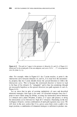
Figure 6.11 The path in C-space in the presence of obstacles O 2 and O 3 of Figure 6.2;
SHabcLdeT is the actual path of the arm endpoint, and curve S H a .. .T is its projection
onto the plane (l 1 ,l 2 ).
other. For example, when in Figure 6.11 the C-point reaches, at point b,the
intersection curve between obstacles O 2 and O 3 , it is clear from the monotonic-
ity property that the C-point should choose the upward direction to follow the
intersection curve. This is because the downward direction is known to lead
to the base of the obstacle O 2 “stalagmite” and is thus less promising (though
not necessarily hopeless) as the upward direction (see path segments bc and cL,
Figure 6.11).
Let us stress that in spite of seeming multiplicity of cases and described
elemental strategies, their logic is the same: All elemental strategies force the C-
point to move either along the M-line, or along the intersection curves between
a C-obstacle and a plane (M-plane, V-plane, or C-space side planes), or along
the intersection curves between two Type III C-obstacles. Depending on the real
workspace obstacles, various combinations of such path segments may occur. We
will show in the next section that if in a given scene there exists a path to the
target position, a combination of elemental strategies is sufficient to produce one.