
Page 332 - Sensing, Intelligence, Motion : How Robots and Humans Move in an Unstructured World
P. 332
THREE-LINK XXP ARM MANIPULATORS 307
The following notation is used throughout this section:
3
• X, Y ⊂ are point sets.
• ∂X denotes the boundary of X.
∼
• X = Y means X is homeomorphic to Y.
• X includes the closure of X, X = X ∪ ∂X.
1 1 n
• For convenience, define the closure of R = R ∪{−∞, +∞} and R =
1 1
R ×· · · × R .
n n
• It is obvious that R = I .
∼
6.3.1 Robot Arm Representation Spaces
To recap some notations introduced earlier, a three-joint XXP robot arm manip-
ulator is an open kinematic chain consisting of three links, L i ,and three joints,
J i , i = 1, 2, 3; J i also denotes the center point of joint J i , defined as the inter-
section point between the axes of joints J i−1 and J i . Joints J 1 and J 2 can be
of either prismatic (sliding) or revolute type, while joint J 3 is of prismatic type.
Joint J 1 is attached to the base O and is the origin of the fixed reference system.
Figures 6.1a–d depict XXP arm configurations. Let p denote the arm end point;
θ i , a revolute joint variable, l i , a prismatic joint variable, and j i , either one of
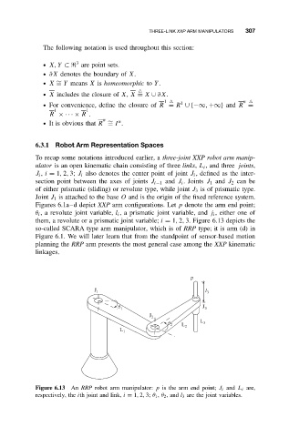
them, a revolute or a prismatic joint variable; i = 1, 2, 3. Figure 6.13 depicts the
so-called SCARA type arm manipulator, which is of RRP type; it is arm (d) in
Figure 6.1. We will later learn that from the standpoint of sensor-based motion
planning the RRP arm presents the most general case among the XXP kinematic
linkages.
p
J 1 l 3
q 1 J 3
J 2
q 2 L L 3
L 1 2
Figure 6.13 An RRP robot arm manipulator: p is the arm end point; J i and L i are,
respectively, the ith joint and link, i = 1, 2, 3; θ 1 , θ 2 ,and l 3 are the joint variables.