
Page 329 - Sensing, Intelligence, Motion : How Robots and Humans Move in an Unstructured World
P. 329
304 MOTION PLANNING FOR THREE-DIMENSIONAL ARM MANIPULATORS
(f) The V-plane is encountered. If dist(P c (curr loc), P c (T )) >
dist(P c (H j ), P c (T )), then repeat Step 4. Otherwise, define
L j = curr loc;goto Step3.
Step 5 Motion Along the Intersection Curve Between Two Type III Obsta-
cles. Move along the intersection curve until one of the following occurs:
(a) A wall or a Type I obstacle is encountered. F = F − 1. If F = 0, T
cannot be reached—the procedure terminates. Otherwise, set local dir1
to its opposite; retrace to H j ; repeat Step 5.
(b) The V-plane is encountered. If dist(P c (curr loc), P c (T )) >
dist(P c (H j ), P c (T )), then repeat Step 5. Otherwise, define
L j = curr loc;if AboveMPlane(curr loc) = true, then follow the
intersection curve between the V-plane and the Type III − obstacle.
Otherwise, follow the intersection curve between the V-plane and the
Type III + obstacle. Go to Step 3.
(c) A Type II obstacle is encountered. If AboveMPlane(curr loc) = true,
then follow the intersection curve between the Type II obstacle and the
Type III − obstacle. Otherwise, follow the intersection curve between
the Type II obstacle and the Type III + obstacle; go to Step 4.
6.2.6 Examples
Two examples considered here demonstrate performance of the motion planning
algorithm presented in the previous section. Both examples make use of examples
considered above in the course of the algorithm construction. To simplify the
visualization of algorithm performance and not to overcrowd pictures with the
arm links and joints, only the resulting paths are presented in Figures 6.11 and
6.12. Since for the Cartesian arm the C-space presentation of a path is the same as
the path of the arm end effector in W-space, the paths are shown in C-space only.
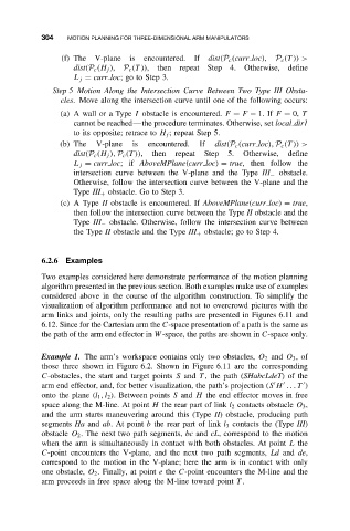
Example 1. The arm’s workspace contains only two obstacles, O 2 and O 3 ,of
those three shown in Figure 6.2. Shown in Figure 6.11 are the corresponding
C-obstacles, the start and target points S and T , the path (SHabcLdeT)ofthe
arm end effector, and, for better visualization, the path’s projection (S H ...T )
onto the plane (l 1 ,l 2 ). Between points S and H the end effector moves in free
space along the M-line. At point H the rear part of link l 2 contacts obstacle O 3 ,
and the arm starts maneuvering around this (Type II) obstacle, producing path
segments Ha and ab. At point b the rear part of link l 3 contacts the (Type III)
obstacle O 2 . The next two path segments, bc and cL, correspond to the motion
when the arm is simultaneously in contact with both obstacles. At point L the
C-point encounters the V-plane, and the next two path segments, Ld and de,
correspond to the motion in the V-plane; here the arm is in contact with only
one obstacle, O 2 . Finally, at point e the C-point encounters the M-line and the
arm proceeds in free space along the M-line toward point T .