
Page 182 - Sensors and Control Systems in Manufacturing
P. 182
Fiber Optics in Sensors and Contr ol Systems
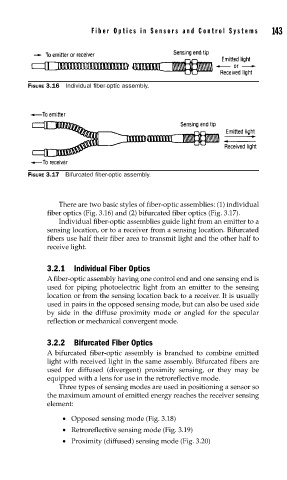
FIGURE 3.16 Individual fi ber-optic assembly. 143
FIGURE 3.17 Bifurcated fi ber-optic assembly.
There are two basic styles of fiber-optic assemblies: (1) individual
fiber optics (Fig. 3.16) and (2) bifurcated fiber optics (Fig. 3.17).
Individual fiber-optic assemblies guide light from an emitter to a
sensing location, or to a receiver from a sensing location. Bifurcated
fibers use half their fiber area to transmit light and the other half to
receive light.
3.2.1 Individual Fiber Optics
A fiber-optic assembly having one control end and one sensing end is
used for piping photoelectric light from an emitter to the sensing
location or from the sensing location back to a receiver. It is usually
used in pairs in the opposed sensing mode, but can also be used side
by side in the diffuse proximity mode or angled for the specular
reflection or mechanical convergent mode.
3.2.2 Bifurcated Fiber Optics
A bifurcated fiber-optic assembly is branched to combine emitted
light with received light in the same assembly. Bifurcated fibers are
used for diffused (divergent) proximity sensing, or they may be
equipped with a lens for use in the retroreflective mode.
Three types of sensing modes are used in positioning a sensor so
the maximum amount of emitted energy reaches the receiver sensing
element:
• Opposed sensing mode (Fig. 3.18)
• Retroreflective sensing mode (Fig. 3.19)
• Proximity (diffused) sensing mode (Fig. 3.20)