
Page 186 - Sensors and Control Systems in Manufacturing
P. 186
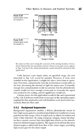
FIGURE 3.23     Fiber Optics in Sensors and Contr ol Systems   147
                          Excess gain curve
                          for sensor 1.


                          FIGURE 3.24
                          Excess gain curve
                          for sensor 3.


                            the sensor as they move along the conveyer at the sensing location. Given a
                            choice between the two proximity sensors (whose excess gain curves appear
                            in Figs. 3.23 and 3.24), which photoelectric control should be selected for this
                            application?

                             If the decision were based solely on specified range, the unit
                          described in Fig. 3.23 would be selected. However, if units were
                          installed in this application, it might fail after a short time in opera-
                          tion. Over time, contaminants from the environment would settle on
                          the lens, decreasing the amount of light the sensor sees. Eventually,
                          enough lens contamination would accumulate that the photoelectric
                          control would not have enough excess gain to overcome the signal
                          loss created by the coating, and the application would fail.
                             A better choice for this application would be the unit represented
                          in Fig. 3.24. It delivers much more excess gain in the operating region
                          required for this application and will therefore work much more suc-
                          cessfully than the other unit.

                          3.3.2 Background Suppression
                          Background suppression enables a diffuse photoelectric sensor to
                          have high excess gain to a predetermined limit and insufficient excess
                          gain beyond that range, where it might pick up objects in motion and
                          yield a false detection. By using triangular ranging, sensor develop-
                          ers have created a sensor that emits light that reflects on the detector
                          from two different target positions. The signal received from the more
                          distant target is subtracted from that of the closer target, providing
                          high excess gain for the closer target.