
Page 205 - Sensors and Control Systems in Manufacturing
P. 205
166
T h ree
Cha p te r
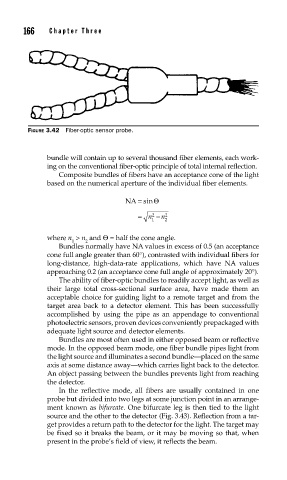
FIGURE 3.42 Fiber-optic sensor probe.
bundle will contain up to several thousand fiber elements, each work-
ing on the conventional fiber-optic principle of total internal reflection.
Composite bundles of fibers have an acceptance cone of the light
based on the numerical aperture of the individual fiber elements.
NA = sinΘ
= n 2 − n 2
1 2
where n > n and Θ = half the cone angle.
1 2
Bundles normally have NA values in excess of 0.5 (an acceptance
cone full angle greater than 60°), contrasted with individual fibers for
long-distance, high-data-rate applications, which have NA values
approaching 0.2 (an acceptance cone full angle of approximately 20°).
The ability of fiber-optic bundles to readily accept light, as well as
their large total cross-sectional surface area, have made them an
acceptable choice for guiding light to a remote target and from the
target area back to a detector element. This has been successfully
accomplished by using the pipe as an appendage to conventional
photoelectric sensors, proven devices conveniently prepackaged with
adequate light source and detector elements.
Bundles are most often used in either opposed beam or reflective
mode. In the opposed beam mode, one fiber bundle pipes light from
the light source and illuminates a second bundle—placed on the same
axis at some distance away—which carries light back to the detector.
An object passing between the bundles prevents light from reaching
the detector.
In the reflective mode, all fibers are usually contained in one
probe but divided into two legs at some junction point in an arrange-
ment known as bifurcate. One bifurcate leg is then tied to the light
source and the other to the detector (Fig. 3.43). Reflection from a tar-
get provides a return path to the detector for the light. The target may
be fixed so it breaks the beam, or it may be moving so that, when
present in the probe’s field of view, it reflects the beam.