
Page 201 - Sensors and Control Systems in Manufacturing
P. 201
162
T h ree
Cha p te r
TRANSMITTER RECEIVER
0–10 V
ANALOG FIBER
A/D MUX XTMR RCVR DEMUX D/A
DIGITAL
BINARY
OUTPUT 0–10 V
ANALOG
OUTPUT
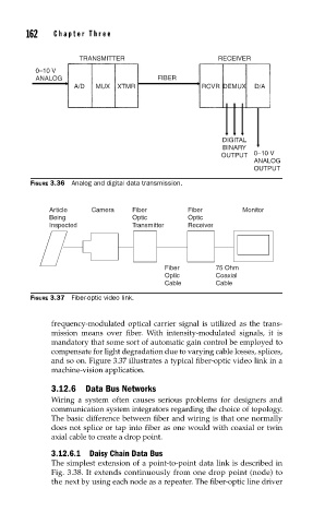
FIGURE 3.36 Analog and digital data transmission.
Article Camera Fiber Fiber Monitor
Being Optic Optic
Inspected Transmitter Receiver
Fiber 75 Ohm
Optic Coaxial
Cable Cable
FIGURE 3.37 Fiber-optic video link.
frequency-modulated optical carrier signal is utilized as the trans-
mission means over fiber. With intensity-modulated signals, it is
mandatory that some sort of automatic gain control be employed to
compensate for light degradation due to varying cable losses, splices,
and so on. Figure 3.37 illustrates a typical fiber-optic video link in a
machine-vision application.
3.12.6 Data Bus Networks
Wiring a system often causes serious problems for designers and
communication system integrators regarding the choice of topology.
The basic difference between fiber and wiring is that one normally
does not splice or tap into fiber as one would with coaxial or twin
axial cable to create a drop point.
3.12.6.1 Daisy Chain Data Bus
The simplest extension of a point-to-point data link is described in
Fig. 3.38. It extends continuously from one drop point (node) to
the next by using each node as a repeater. The fiber-optic line driver