
Page 196 - Sensors and Control Systems in Manufacturing
P. 196
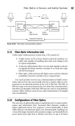
Electrical       Fiber Optics in Sensors and Contr ol Systems     157
                                                        Light Pulse
                                       Light Pulse
                                                                             Electrical
                       Pulse                                                  Pulse
                        In                                                     Out
                               Electrical                          Light
                               To                                  To
                               Light                               Electrical
                               Conversion                          Conversion
                                            LED          Photo
                                            Light Source  Detector

                                            Electrical Pulse Out
                                          Equals Electrical Pulse In
                     FIGURE 3.32  Fiber-optic communication system.


                     3.11  Fiber-Optic Information Link
                          A fiber-optic communication system (Fig. 3.32) consists of:

                              •  A light source (LED or laser diode) pulsed by interface cir-
                                 cuitry and capable of handling data rates and voltage levels
                                 of a given magnitude.
                              •  A detector (photodiode) that converts light signals to electri-
                                 cal signals and feeds interface circuitry to re-create the origi-
                                 nal electrical signal.
                              •  Fiber-optic cables between the light source and the detector
                                 (called the transmitter and the receiver, respectively).
                             It is usual practice for two-way communication to build a trans-
                          mitter and receiver into one module and use a duplex cable to com-
                          municate to an identical module at the end of the link. The 820- to
                          850-nm range is the most frequent for low-data-rate communication,
                          but other wavelengths (1300 and 1550 nm) are used in long-distance
                          systems. Fiber selection must always take transmission wavelength
                          into consideration.


                     3.12  Configurations of Fiber Optics
                          The selection of optical fiber plays a significant part in sensor perfor-
                          mance and information flow. Increased fiber diameter results in
                          higher delivered power, but supports a lower bandwidth. A fiber
                          with a 200-μm core diameter (glass core, silicone plastic cladding), by
                          virtue of its larger diameter and acceptance angle, can transmit five to
                          seven times more light than a 100-μm core fiber, or up to 30 times