
Page 199 - Sensors and Control Systems in Manufacturing
P. 199
160
T h ree
Cha p te r
FIBER
FIBER OPTIC FIBER OPTIC
ENCODER FIBER ENCODER
LINK FIBER LINK
TRANSMITTER RECEIVER
NOISE IMMUNE
3300 FEET
5 Mbit/CHANNEL
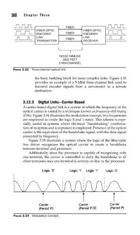
FIGURE 3.33 Three-channel optical link.
the basic building block for more complex links. Figure 3.33
provides an example of a 5-Mbit three-channel link used to
transmit encoder signals from a servomotor to a remote
destination.
3.12.3 Digital Links—Carrier-Based
A carrier-based digital link is a system in which the frequency of the
optical carrier is varied by a technique known as frequency-shift keying
(FSK). Figure 3.34 illustrates the modulation concept; two frequencies
are employed to create the logic 0 and 1 states. This scheme is espe-
cially useful in systems where electrical “handshaking” (confirma-
tion of reception and acceptance) is employed. Presence of the optical
carrier is the equivalent of the handshake signal, with the data signal
presented by frequency.
Figure 3.35 illustrates a system where the logic of the fiber-optic
line driver recognizes the optical carrier to create a handshake
between terminal and processor.
Additionally, since the processor is capable of recognizing only
one terminal, the carrier is controlled to deny the handshake to all
other terminals once one terminal is actively on-line to the processor.
FIGURE 3.34 Modulation concept.