
Page 203 - Sensors and Control Systems in Manufacturing
P. 203
164
Cha p te r
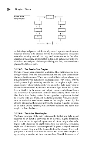
FIGURE 3.40 T h ree
Ring coupler.
sufficient optical power to tolerate a bypassed repeater. Another con-
tingency method is to provide for the transmitting node to read its
own data coming around the ring, and to retransmit in the other
direction if necessary, as illustrated in Fig. 3.40. Yet another is to pro-
vide for a second pair of fibers paralleling the first, but routed on a
physically different path.
3.12.6.3 The Passive Star Coupler
Certain systems have attempted to utilize a fiber-optic coupling tech-
nology offered from the telecommunications and data communica-
tions applications areas. When successful, this technique allows tap-
ping into fiber-optic trunk lines, a direct parallel with coaxial or twin
axial systems. Light entering into the tap or coupler is split into a
given number of output channels. The amount of light in any output
channel is determined by the total amount of light input, less system
losses, divided by the number of output channels. Additional losses
are incurred at the junction of the main data-carrying fibers with the
fiber leads from the tap or star. As such, passive couplers are limited
to systems with few drops and moderate distances. Also, it is impor-
tant to minimize termination losses at the coupler caused by the
already diminished light output from the coupler. A partial solution
is an active in-line repeater, but a superior solution, the active star
coupler, is described next.
3.12.6.4 The Active Star Coupler
The basic principle of the active star coupler is that any light signal
received as an input is converted to an electrical signal, amplified,
and reconverted to optical signals on all other output channels.
Figure 3.41 illustrates an eight-port active star coupler, containing
eight sets of fiber-optic input/output (I/O) ports. A signal received
on the channel 1 input will be transmitted on the channel 2 to 8 out-
put ports. One may visualize the use of the active star coupler as
aggregating a number of taps into one box. Should the number of