
Page 418 - Sensors and Control Systems in Manufacturing
P. 418
372
Cha p te r
FIGURE 7.46 Se v e n Contilever
Cantilever-type Dielectric
acceleration mirror
sensor.
Glass
Neodymium
doped glass
Fiber
by photoluminescence of a neodymium-doped glass element placed
close to the sensor end of the fiber.
The optoelectronic detector module has two optical filters to sep-
arate the signals λ and λ and two photodiodes to convert the signal
s r
and the reference light into separate analog voltages. The signal pro-
cessing for compensation is then merely a matter of electrical division.
2
2
A measuring range of 0.1 to 700 m/s and a resolution of 0.1 m/s is
obtained over the frequency range of 5 to 800 Hz.
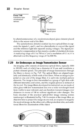
7.29 An Endoscope as Image Transmission Sensor
An imaging cable consists of numerous optical fibers, typically 3000
to 100,000, each of which has a diameter of 10 μm and constitutes a
picture element (pixel). The principle of image transmission through
the fibers is shown in Fig. 7.47. The optical fibers are aligned regu-
larly and identically at both ends of the fibers. When an image is pro-
jected on one end of the image fiber, it is split into multiple picture
elements. The image is then transmitted as a group of light dots with
different intensities and colors, and the original picture is reduced at
the far end. The image fibers developed for industrial use are made of
silica glass with low transmission loss over a wide wavelength band
from visible to near infrared, and can therefore transmit images over
distances in excess of 100 m without significant color changes. The
basic structure of the practical optical-fiber image sensing system
(endoscope) is illustrated in Fig. 7.48. It consists of the image fiber, an
objective lens to project the image on one end, an eyepiece to magnify
the received image on the other end, a fiber protection tube, and addi-
tional fibers for illumination of the object.
FIGURE 7.47 Image transmission through an image fi ber.