
Page 414 - Sensors and Control Systems in Manufacturing
P. 414
368
Se v e n
Cha p te r
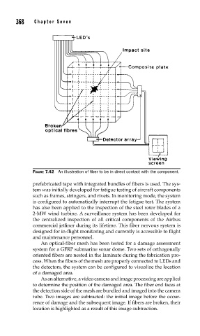
FIGURE 7.42 An illustration of fi ber to be in direct contact with the component.
prefabricated tape with integrated bundles of fibers is used. The sys-
tem was initially developed for fatigue testing of aircraft components
such as frames, stringers, and rivets. In monitoring mode, the system
is configured to automatically interrupt the fatigue test. The system
has also been applied to the inspection of the steel rotor blades of a
2-MW wind turbine. A surveillance system has been developed for
the centralized inspection of all critical components of the Airbus
commercial jetliner during its lifetime. This fiber nervous system is
designed for in-flight monitoring and currently is accessible to flight
and maintenance personnel.
An optical-fiber mesh has been tested for a damage assessment
system for a GFRP submarine sonar dome. Two sets of orthogonally
oriented fibers are nested in the laminate during the fabrication pro-
cess. When the fibers of the mesh are properly connected to LEDs and
the detectors, the system can be configured to visualize the location
of a damaged area.
As an alternative, a video camera and image processing are applied
to determine the position of the damaged area. The fiber end faces at
the detection side of the mesh are bundled and imaged into the camera
tube. Two images are subtracted: the initial image before the occur-
rence of damage and the subsequent image. If fibers are broken, their
location is highlighted as a result of this image subtraction.