
Page 525 - Sensors and Control Systems in Manufacturing
P. 525
478
Cha p te r
Ni ne
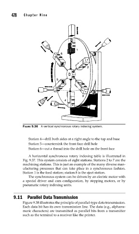
FIGURE 9.36 A vertical synchronous rotary indexing system.
Station 4—drill both sides at a right angle to the top and base
Station 5—countersink the front face drill hole
Station 6—cut a thread into the drill hole on the front face
A horizontal synchronous rotary indexing table is illustrated in
Fig. 9.37. This system consists of eight stations. Stations 2 to 7 are the
machining stations. This is just an example of the many diverse man-
ufacturing processes that can take place in a synchronous fashion.
Station 1 is the feed station; station 8 is the eject station.
The synchronous system can be driven by an electric motor with
a special driver and cam configuration, by stepping motors, or by
pneumatic rotary indexing units.
9.11 Parallel Data Transmission
Figure 9.38 illustrates the principle of parallel-type data transmission.
Each data bit has its own transmission line. The data (e.g., alphanu-
meric characters) are transmitted as parallel bits from a transmitter
such as the terminal to a receiver like the printer.