
Page 520 - Sensors and Control Systems in Manufacturing
P. 520
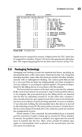
FIGURE 9.30  Allocation list.             Communications     473

                          Inputs must be assigned to sensors. Outputs from the PLC must also
                          be assigned to actuators. Figure 9.30 shows the appropriate allocation
                          lists. The sequencing program for the feed unit is shown in Fig. 9.31.


                     9.8 Packaging Technology
                          Arranging and feeding of parts for insertion into boxes, including an
                          intermediate layer, with a feed unit is illustrated in Fig. 9.32. Using this
                          inserting machine, many other functions are carried out either simulta-
                          neously with or subsequent to feeding. The various parts that are fed
                          by a conveyer belt are lined up independently and then arranged in
                          rows by actuator A, according to a specific pattern. The parts are trans-
                          ferred by the lifting device in accordance with this pattern.
                             The horizontal movement of the feed unit is executed by actuator
                          B; the vertical movement, by actuators C and D. In the position shown
                          in the diagram, the parts picked up by the lifting device are inserted
                          into the box by extending actuator D. At the same time, actuator C
                          also extends and picks up a square board that is used as an intermedi-
                          ate layer as two layers of parts are being inserted. As soon as actuator
                          C has retracted, holding the intermediate layer, the device is moved
                          by the indexing actuator B. The end position actuator C located above
                          the box and actuator D located above the collection point are used for
                          the arrangement of parts.
                             When actuator C has extended, the intermediate layer is inserted
                          and the next layer of parts is taken up by actuator D. When actuator
                          B retracts, the position drawn is reached once again and the second
                          layer is inserted into the box. Then, when actuator B extends once
                          again, an intermediate layer is placed on the second layer and the
                          next parts are picked up.