
Page 517 - Sensors and Control Systems in Manufacturing
P. 517
470
Ni ne
Cha p te r
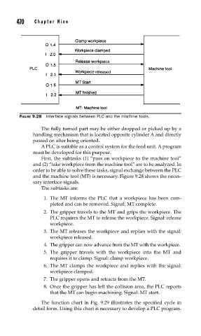
FIGURE 9.28 Interface signals between PLC and the machine tools.
The fully turned part may be either dropped or picked up by a
handling mechanism that is located opposite cylinder A and directly
passed on after being oriented.
A PLC is suitable as a control system for the feed unit. A program
must be developed for this purpose.
First, the subtasks (1) “pass on workpiece to the machine tool”
and (2) “take workpiece from the machine tool” are to be analyzed. In
order to be able to solve these tasks, signal exchange between the PLC
and the machine tool (MT) is necessary. Figure 9.28 shows the neces-
sary interface signals.
The subtasks are:
1. The MT informs the PLC that a workpiece has been com-
pleted and can be removed. Signal: MT complete.
2. The gripper travels to the MT and grips the workpiece. The
PLC requires the MT to release the workpiece. Signal: release
workpiece.
3. The MT releases the workpiece and replies with the signal:
workpiece released.
4. The gripper can now advance from the MT with the workpiece.
5. The gripper travels with the workpiece into the MT and
requires it to clamp. Signal: clamp workpiece.
6. The MT clamps the workpiece and replies with the signal:
workpiece clamped.
7. The gripper opens and retracts from the MT.
8. Once the gripper has left the collision area, the PLC reports
that the MT can begin machining. Signal: MT start.
The function chart in Fig. 9.29 illustrates the specified cycle in
detail form. Using this chart is necessary to develop a PLC program.