
Page 565 - Sensors and Control Systems in Manufacturing
P. 565
518
Cha p te r
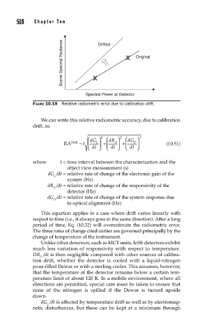
Scene Spectral Radiance T e n x Drifted x Original
Spectral Power at Detector
FIGURE 10.19 Relative radiometric error due to calibration drift.
We can write this relative radiometric accuracy, due to calibration
drift, as:
⎛ dG ⎞ 2 ⎛ dR ⎞ 2 ⎛ dG ⎞ 2
RA Drift ≈ t ⎜ E ⎟ +⎜ D ⎟ +⎜ O ⎟ (10.51)
⎝ dt ⎠ ⎝ dt ⎠ ⎝ dt ⎠
where t = time interval between the characterization and the
object view measurement (s)
dG /dt = relative rate of change of the electronic gain of the
E
system (Hz)
dR /dt = relative rate of change of the responsivity of the
D
detector (Hz)
dG /dt = relative rate of change of the system response due
O
to optical alignment (Hz)
This equation applies to a case where drift varies linearly with
respect to time (i.e., it always goes in the same direction). After a long
period of time, Eq. (10.32) will overestimate the radiometric error.
The three rates of change cited earlier are governed principally by the
change of temperature of the instrument.
Unlike other detectors, such as MCT units, InSb detectors exhibit
much less variation of responsivity with respect to temperature.
DR /dt is then negligible compared with other sources of calibra-
D
tion drift, whether the detector is cooled with a liquid-nitrogen
pour-filled Dewar or with a sterling cooler. This assumes, however,
that the temperature of the detector remains below a certain tem-
perature limit of about 120 K. In a mobile environment, where all
directions are permitted, special care must be taken to ensure that
none of the nitrogen is spilled if the Dewar is turned upside
down.
dG /dt is affected by temperature drift as well as by electromag-
E
netic disturbances, but these can be kept at a minimum through