
Page 566 - Sensors and Control Systems in Manufacturing
P. 566
SpectRx NIR Technology
Scene Spectral Radiance Spectral Range of Interest 519
x
Nonlinear
Linear
x
Spectral Power at Detector
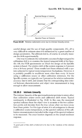
FIGURE 10.20 Relative radiometric error due to intrinsic linearity errors.
careful design and the use of high-quality components. DG /dt is
O
very difficult to estimate since it is influenced by a great number of
design parameters. The ultimate test is, of course, to actually meas-
ure the drift experimentally.
One way to estimate the radiometric accuracy budget assigned to
calibration drift is to examine the typical temporal drift of the Spec-
tRx 100, the FTIR spectrometer on which the design of the SpectRx
system is based. The relative drift of the system response is 2 percent
3
over a 16-hour period. These results have been obtained with a sys-
tem subjected to typical room-temperature fluctuations. However, it
is probably possible to recalibrate more often than every 16 hours
using a calibration source or other calibration references. For the
SpectRx system, we typically use 2 percent as the relative radiometric
accuracy due to drift, and assume that the corresponding time inter-
val between characterization and object view measurement is long
enough to allow measurement.
10.10.3 Intrinsic Linearity
The intrinsic linearity of the spectroradiometer pertains to errors other
than calibration source errors and calibration drift errors. Typical
nonlinearity is illustrated in Fig. 10.20. In this case, the measured
spectral radiance from the object view is accurate at the two calibra-
tion points and deviates from the true values when we move away
from these points. For this type of error, it is advantageous to choose
a calibration source temperature, so the spectral radiance of the cali-
bration measurements is included in the range of the spectral radiance
to be measured. The exact location depends on the actual nonlinear
response.
3 A good part of this drift is believed to be due to the variation of the internal
source.