
Page 122 - Separation process engineering
P. 122
Chapter 3. Introduction to Column Distillation
Distillation is by far the most common separation technique in the chemical process industry, accounting
for 90% to 95% of the separations. The approximately 40,000 distillation columns in use account for
approximately 40% of the energy use by the United States’ chemical process industry—equivalent to a
staggering 1.2 million barrels of crude oil a day (Humphrey and Keller, 1997).
This chapter introduces how continuous distillation columns work and serves as the lead to a series of
nine chapters on distillation. The basic calculation procedures for binary distillation are developed in
Chapter 4. Multicomponent distillation is introduced in Chapter 5, detailed computer calculation
procedures for these systems are developed in Chapter 6, and simplified shortcut methods are covered in
Chapter 7. More complex distillation operations such as extractive and azeotropic distillation are the
subject of Chapter 8. Chapter 9 switches to batch distillation, which is commonly used for smaller
systems. Detailed design procedures for both staged and packed columns are discussed in Chapter 10.
Finally, Chapter 11 looks at the economics of distillation and methods to save energy (and money) in
distillation systems.
3.1 Developing a Distillation Cascade
In Chapter 2, we learned how to do the calculations for flash distillation. Flash distillation is a very
simple unit operation, but in most cases it produces a limited amount of separation. In Problems 2.D2,
2.D5, and 2.F2 we saw that more separation could be obtained by adding on (or cascading) more flash
separators. The cascading procedure can be extended into a process that produces one pure vapor and one
pure liquid product. First, we could send the vapor streams to additional flash chambers at increasing
pressures and the liquid streams to flash chambers with decreasing pressures, as shown in Figure 3-1.
Stream V will have a high concentration of the more volatile component, and stream L will have a low
5
1
concentration of the more volatile component. Each flash chamber in Figure 3-1 can be analyzed by the
methods developed previously.
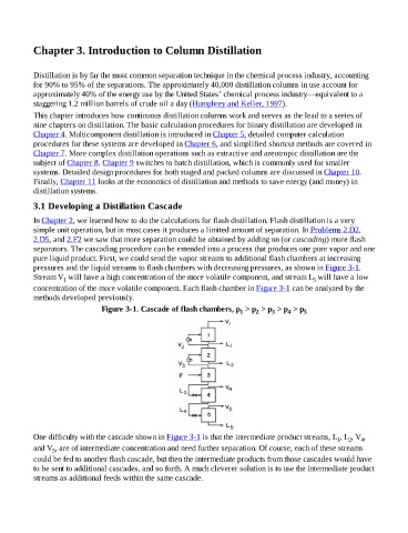
Figure 3-1. Cascade of flash chambers, p > p > p > p > p 5
1
4
3
2
One difficulty with the cascade shown in Figure 3-1 is that the intermediate product streams, L , L , V ,
4
2
1
and V , are of intermediate concentration and need further separation. Of course, each of these streams
5
could be fed to another flash cascade, but then the intermediate products from those cascades would have
to be sent to additional cascades, and so forth. A much cleverer solution is to use the intermediate product
streams as additional feeds within the same cascade.