
Page 127 - Separation process engineering
P. 127
The cascade shown in Figure 3-6 is the usual form in which distillation is done. Because of the repeated
vaporizations and condensations as we go up the column, the top product (distillate) can be highly
concentrated in the more volatile component. The section of the column above the feed stage is known as
the enriching or rectifying section. The bottom product (bottoms) is highly concentrated in the less
volatile component, since the more volatile component has been stripped out by the rising vapors. This
section is called the stripping section.
The distillation separation works because every time we vaporize material the more volatile component
tends to concentrate in the vapor, and the less volatile component in the liquid. As the relative volatility α,
Eq. (2-21), of the system decreases, distillation becomes more difficult. If α = 1.0, the liquid and vapor
will have the same composition, and no separation will occur. Liquid and vapor also have the same
composition when an azeotrope occurs. In this case one can approach the azeotrope concentration at the
top or bottom of the column but cannot get past it except with a heterogeneous azeotrope (see Chapter 8).
The third limit to distillation is the presence of either chemical reactions between components or
decomposition reactions. This problem can often be controlled by operating at lower temperatures and
using vacuum or steam distillation (see Chapter 8).
While we are still thinking of flash distillation chambers, a simple but useful result can be developed. In a
flash chamber a component will tend to exit in the vapor if y V > x L. Rearranging this, if KV/L > 1 a
i
i
i
component tends to exit in the vapor. In a distillation column this means that components with KV/L > 1
i
tend to exit in the distillate, and components with KV/L < 1 tend to exit in the bottoms. This is only a
i
qualitative guide, since the separation on each stage is far from perfect, and K, V, and L all vary in the
i
column; however, it is useful to remember.
3.2 Distillation Equipment
It will be helpful for you to have a basic understanding of distillation equipment before studying the
design methods. A detailed description of equipment is included in Chapter 10. Figure 3-6A is a
schematic of a distillation column, and Figure 3-6B is a photograph of several columns.
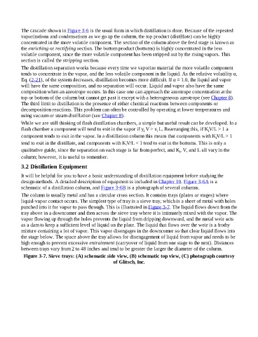
The column is usually metal and has a circular cross section. It contains trays (plates or stages) where
liquid-vapor contact occurs. The simplest type of tray is a sieve tray, which is a sheet of metal with holes
punched into it for vapor to pass through. This is illustrated in Figure 3-7. The liquid flows down from the
tray above in a downcomer and then across the sieve tray where it is intimately mixed with the vapor. The
vapor flowing up through the holes prevents the liquid from dripping downward, and the metal weir acts
as a dam to keep a sufficient level of liquid on the plate. The liquid that flows over the weir is a frothy
mixture containing a lot of vapor. This vapor disengages in the downcomer so that clear liquid flows into
the stage below. The space above the tray allows for disengagement of liquid from vapor and needs to be
high enough to prevent excessive entrainment (carryover of liquid from one stage to the next). Distances
between trays vary from 2 to 48 inches and tend to be greater the larger the diameter of the column.
Figure 3-7. Sieve trays: (A) schematic side view, (B) schematic top view, (C) photograph courtesy
of Glitsch, Inc.