
Page 123 - Separation process engineering
P. 123
Consider stream L , which was generated by flashing part of the feed stream and then condensing part of
2
the resulting vapor. Since the material in L has been vaporized once and condensed once, it probably has
2
a concentration close to that of the original feed stream. (To check this, you can do the appropriate flash
calculation on a McCabe-Thiele diagram.) Thus, it is appropriate to use L as an additional feed stream to
2
stage 3. However, since p > p , its pressure must first be decreased.
3
2
Stream L is the liquid obtained by partially condensing V , the vapor obtained from flashing vapor
1
2
stream V . After one vaporization and then a condensation, stream L will have a concentration close to
1
3
that of stream V . Thus it is appropriate to use stream L as an additional feed to stage 2 after pressure
1
3
reduction.
A similar argument can be applied to the intermediate vapor products below the feed, V and V . V was
5
4
4
obtained by partially condensing the feed stream and then partially vaporizing the resulting liquid. Since
its concentration is approximately the same as the feed, stream V can be used as an additional feed to
4
stage 3 after compression to a higher pressure. By the same reasoning, stream V can be fed to stage 4.
5
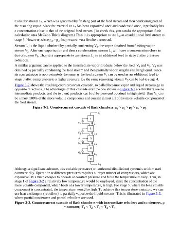
Figure 3-2 shows the resulting countercurrent cascade, so called because vapor and liquid streams go in
opposite directions. The advantages of this cascade over the one shown in Figure 3-1 are that there are no
intermediate products, and the two end products can both be pure and obtained in high yield. Thus V can
1
be almost 100% of the more volatile components and contain almost all of the more volatile component of
the feed stream.
Figure 3-2. Countercurrent cascade of flash chambers, p > p > p > p > p 5
3
4
2
1
Although a significant advance, this variable pressure (or isothermal distillation) system is seldom used
commercially. Operation at different pressures requires a larger number of compressors, which are
expensive. It is much cheaper to operate at constant pressure and force the temperature to vary. Thus, in
stage 1 of Figure 3-2 a relatively low temperature would be employed, since the concentration of the
more volatile component, which boils at a lower temperature, is high. For stage 5, where the less volatile
component is concentrated, the temperature would be high. To achieve this temperature variation, we can
use heat exchangers (reboilers) to partially vaporize the liquid streams. This is illustrated in Figure 3-3,
where partial condensers and partial reboilers are used.
Figure 3-3. Countercurrent cascade of flash chambers with intermediate reboilers and condensers, p
= constant; T < T < T < T < T 5
1
4
3
2